electronics
Difficulty Levels:
1
Q&A
Medium
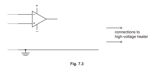
An op-amp is to be used to switch on a high-voltage heater.
(i)State the name of the component used as the output device of the op-amp.[1]
(ii)Complete Fig.$$7.3$$ using the device named in(i)and a diode so that the heater may be switched on when the output of the op-amp is positive.
Answer:
(i)relay coil
(ii)relay coil between op-amp and earth
diode with correct polarity(pointing away from output)connected between output and device and no other connections or diode with correct polarity(pointing towards earth)between device and earth and no other connections
switch connected to high voltage circuit
Explanation:
2
Q&A
Medium
Fig.$$7.1$$ shows the circuit diagram containing an operational amplifier(op-amp).
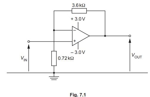 (i)State the name of this type of amplifier.
(ii)Show that the gain of the amplifier is $$6.0$$.
(iii)At time $$t=0$$ the input potential $$V_{I N}$$ is zero.$$V_{\mathbb{N}}$$ then gradually increases with time $$t$$ as shown in Fig.$$7.2$$
(i)State the name of this type of amplifier.
(ii)Show that the gain of the amplifier is $$6.0$$.
(iii)At time $$t=0$$ the input potential $$V_{I N}$$ is zero.$$V_{\mathbb{N}}$$ then gradually increases with time $$t$$ as shown in Fig.$$7.2$$
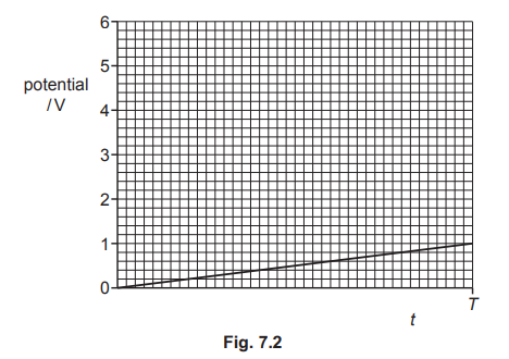 On Fig.$$7.2$$ sketch a line to show the variation with time $$t$$ of the output potential $$V_{\text {OUT }}$$ from time $$t=0$$ to time $$t=T$$.[2]
(iv)State how the circuit of Fig.$$7.1$$ may be changed so that the gain of the amplifier is dependent on light intensity.
On Fig.$$7.2$$ sketch a line to show the variation with time $$t$$ of the output potential $$V_{\text {OUT }}$$ from time $$t=0$$ to time $$t=T$$.[2]
(iv)State how the circuit of Fig.$$7.1$$ may be changed so that the gain of the amplifier is dependent on light intensity.
(i)State the name of this type of amplifier.
(ii)Show that the gain of the amplifier is $$6.0$$.
(iii)At time $$t=0$$ the input potential $$V_{I N}$$ is zero.$$V_{\mathbb{N}}$$ then gradually increases with time $$t$$ as shown in Fig.$$7.2$$
On Fig.$$7.2$$ sketch a line to show the variation with time $$t$$ of the output potential $$V_{\text {OUT }}$$ from time $$t=0$$ to time $$t=T$$.[2]
(iv)State how the circuit of Fig.$$7.1$$ may be changed so that the gain of the amplifier is dependent on light intensity.
Answer:
(i)non-inverting(amplifier)
(ii)gain $$=\frac{R_{f}}{R}+1$$
gain $$=\frac{3.6}{0.72}+1=6.0$$
(iii)straight line from $$(0,0)$$ to $$(T / 2,3)$$
line from origin to $$3.0 \mathrm{~V}$$ then horizontal line at $$3.0 \mathrm{~V}$$ to $$T$$
(iv)Idr / light dependent resistor replaces one of the two resistors
Explanation:
3
Q&A
Medium
Answer:
Not available
Explanation: